|
|
|
0 members (),
34
guests, and
3
robots. |
|
Key:
Admin,
Global Mod,
Mod
|
|
|
S |
M |
T |
W |
T |
F |
S |
|
|
|
1
|
2
|
3
|
4
|
5
|
|
6
|
7
|
8
|
9
|
10
|
11
|
12
|
|
13
|
14
|
15
|
16
|
17
|
18
|
19
|
|
20
|
21
|
22
|
23
|
24
|
25
|
26
|
|
27
|
28
|
29
|
30
|
|
|
|
|
|
Forums13
Topics7,385
Posts40,939
Members10,040
| |
Most Online3,137
Apr 9th, 2026
|
|
|
|
Joined: Mar 2013
Posts: 51
2nd Generation
|
|
2nd Generation
Joined: Mar 2013
Posts: 51 |
I found the rv input relay, yes very hard to notice velcro'd deep in the cop. It has 3 teeminals going in one side, one wire coming out the opposite end. It has a diode soldered on the two outer terminals (which id guess is the coil) and the inner wire had 24v. Under no circumstances was power present at the coil to energize it.
At the hall button interface in the ducting I have 24vdc on the signal wires (twisted pair) from the processor, removing that input from the hall board causes the hallbutton lights to go out, interesting. Apparently this twisted pair should only carry tones (900mhz, 910mhz, etc.) to the tone board to be converted into hall calls, curious as to why it has 24vdc on it?
Makes me think this is a processor issue still.
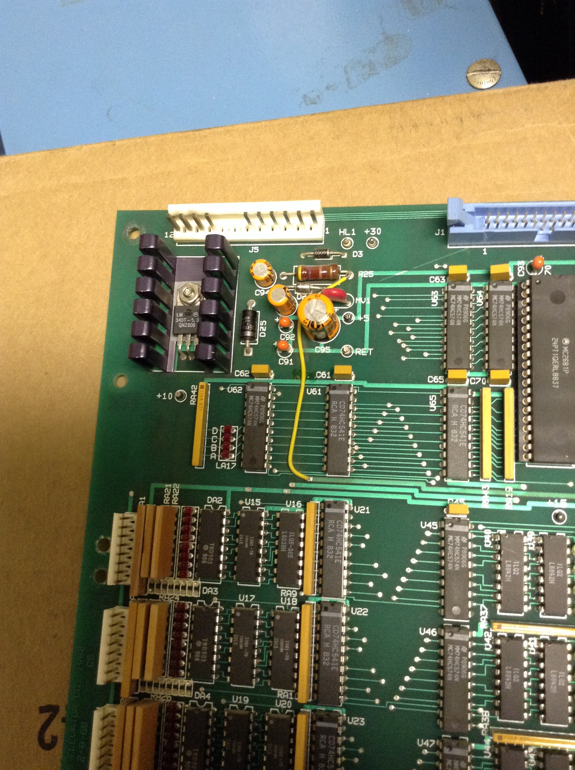
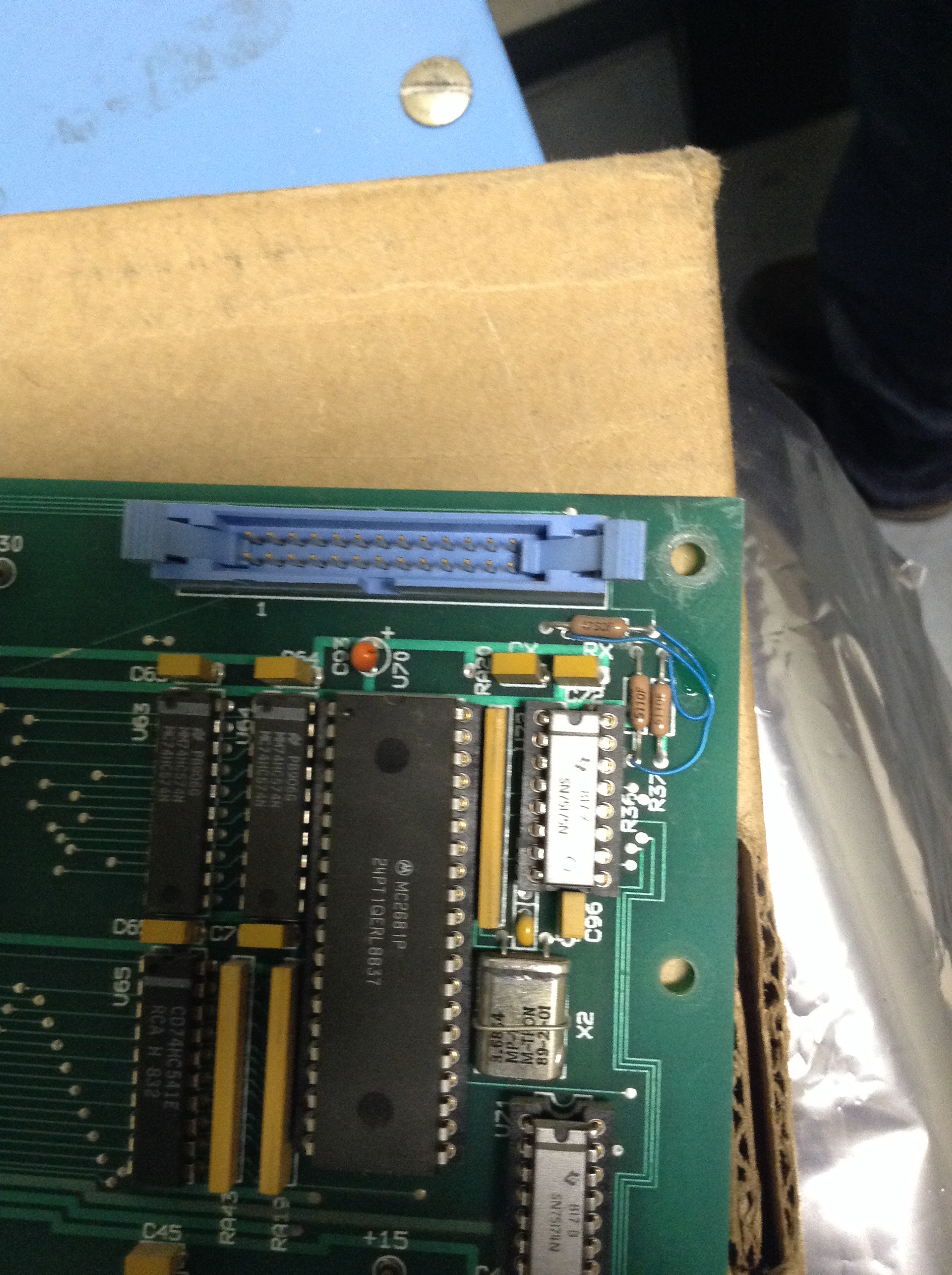
Upon closer inspection my old processor has external jumpers in a few different places not present on the new board. Is it common for otis to make such changes job specific?
Ill attach pictures for reference.
Also found out i only have generic lrv prints, my LRS is considerably different. Lovely.
|
|
|
|
|
Joined: Mar 2013
Posts: 51
2nd Generation
|
|
2nd Generation
Joined: Mar 2013
Posts: 51 |
Yellow Jumper near top of board
Blue Jumpers on resistors
Blue Jumpers on Chip
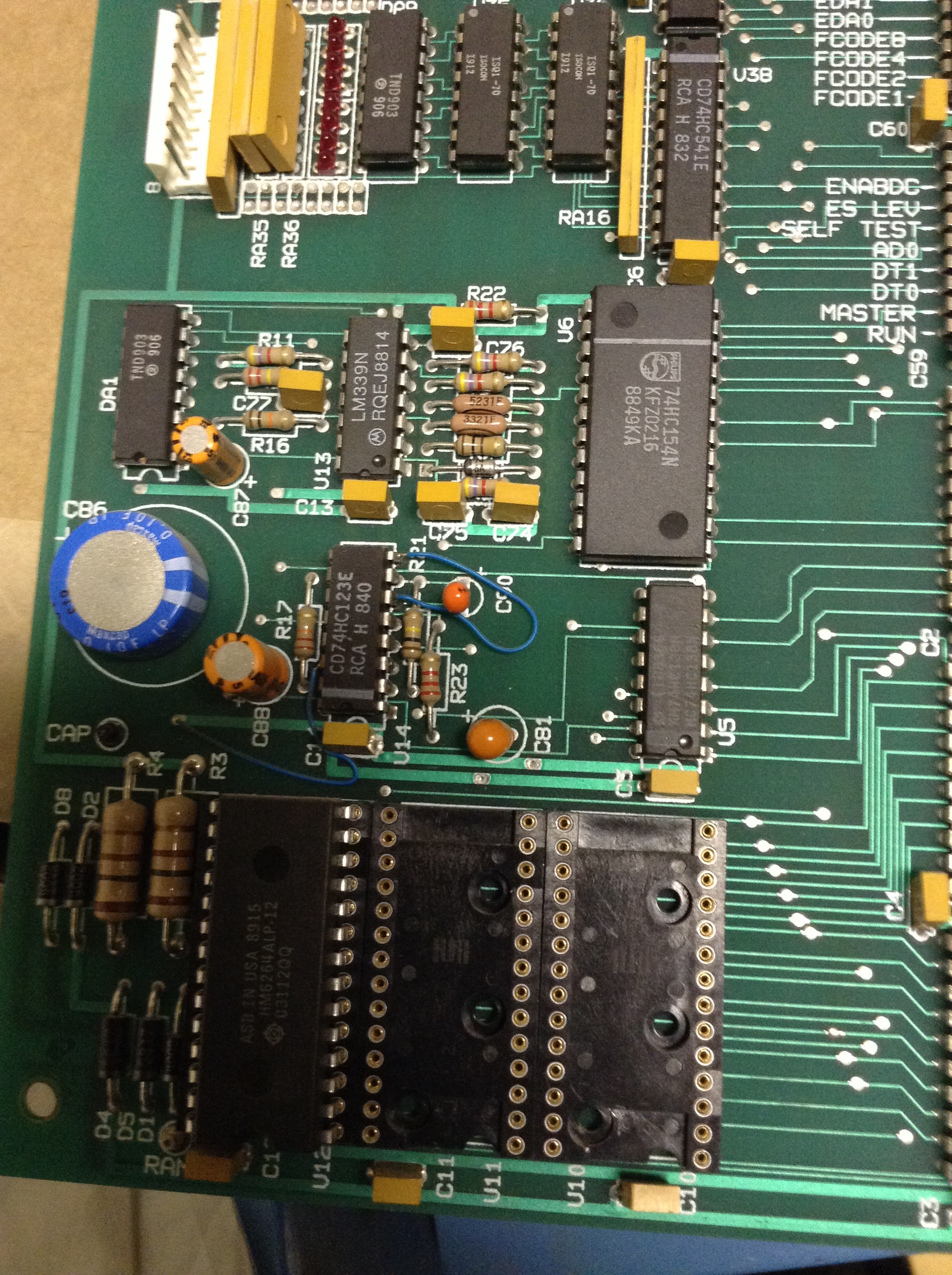
Processor
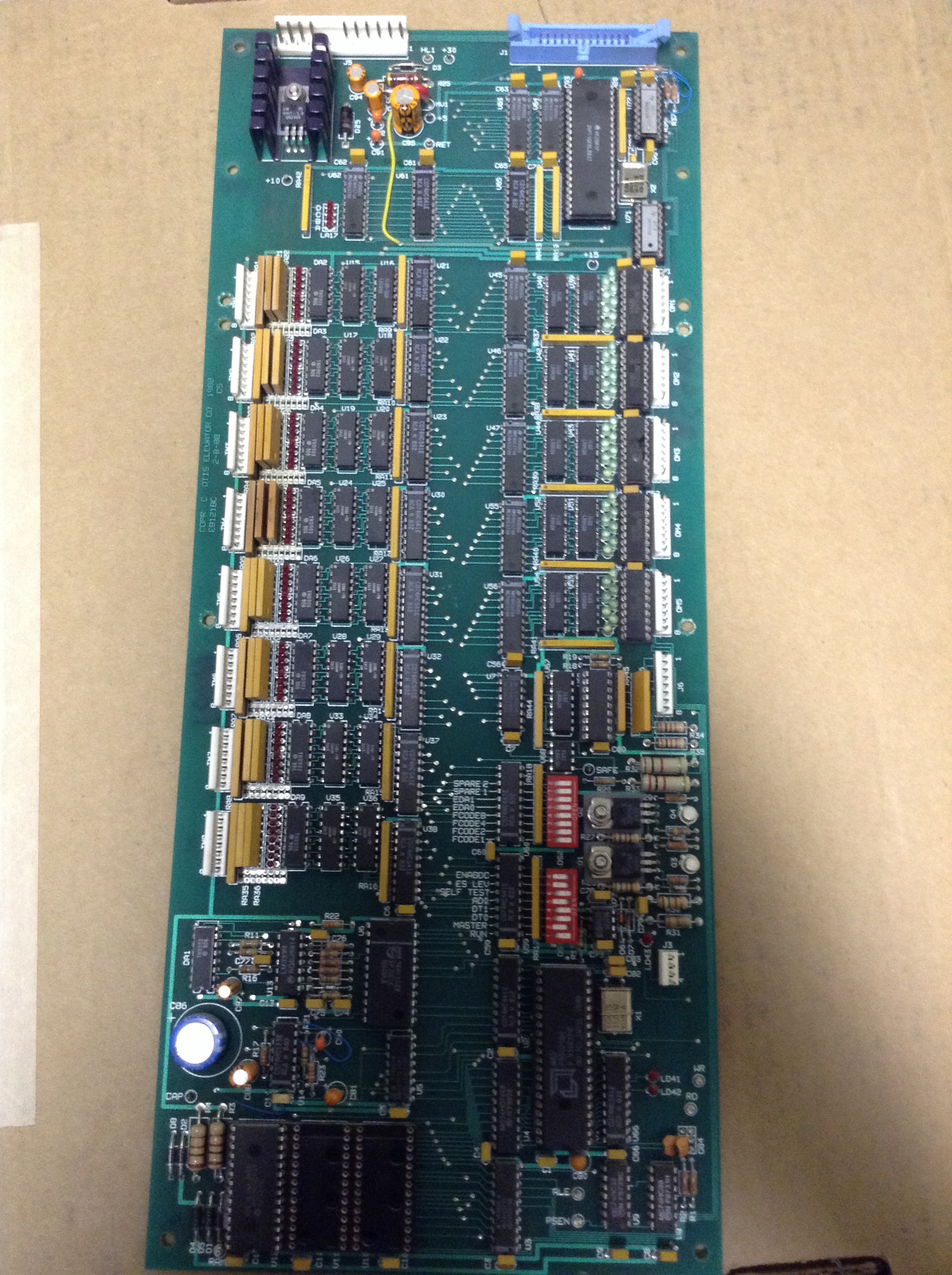
Last edited by rollaway-up; 06/17/14 05:11 AM.
|
|
|
|
|
Joined: Mar 2014
Posts: 68
journeyman
|
|
journeyman
Joined: Mar 2014
Posts: 68 |
Those jumpers do not look normal and are probably there to compensate for other issues. I've seen repair facilities put them on the backside of the board, but not like that.
Unitec also will not sell you certain pages of the schematic specific to your job, you have to buy all 12-15 pages at $80 per page.
Have you tried to swap out the hall button interface board?
|
|
|
|
|
Joined: Jan 2014
Posts: 432
addict
|
|
addict
Joined: Jan 2014
Posts: 432 |
I looked at a few different prints, RV should be picked up. it comes from terminal 90 and 90 gets 24 volts as long as the 24 volt regulator on the relay board is good.
one of my prints shows RV n/0 contact feeding the hall interface board. it supplied 24 volts to what looks like a filter of some kind on the hall board. do you have any wiring diagram numbers on the controller, maybe i can get something close. i would really dig into the rv thing once again. or you can try just jumping out the n/o contact, as that would accomplish the same thing.
|
|
|
|
|
Joined: Jan 2014
Posts: 432
addict
|
|
addict
Joined: Jan 2014
Posts: 432 |
I looked at a few different prints, RV should be picked up. it comes from terminal 90 and 90 gets 24 volts as long as the 24 volt regulator on the relay board is good.
one of my prints shows RV n/0 contact feeding the hall interface board. it supplied 24 volts to what looks like a filter of some kind on the hall board. do you have any wiring diagram numbers on the controller, maybe i can get something close. i would really dig into the rv thing once again. or you can try just jumping out the n/o contact, as that would accomplish the same thing. I'm almost sure, this has something to do with your problem can't see why they would put that little relay there if it was not being used. that is the rv relay, i remember the velcro. could not believe it when i found it.
|
|
|
|
|
|
|
|
|
HW PM
by Chris, January 13
|
|
|
|
|
|
|
|
|
|
|
|