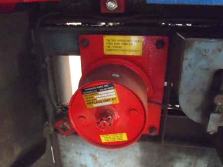
I have a Westinghouse REL job that has the big generators with exciters, regulators. I've heard of this start circuit before (with the starting grid resistors on top of the controllers) where 5 picks and stays picked when 11A picks. I understand the resistors in the 5 side of the circuit limit the inrush and allow the armature to get up to speed and voltage output on the exciter to get up and then 11A picks and 5 stays up. I have no info on the AC windings and connections, the prints just show T1-2-3 going to the AC motor generator. L1, L2 and L3 connect to T1, T2 and T3 and go to the generator AC end and connect to "pairs" of wires which I assume are 1 & 12, 2 & 10 and 3 & 11. I'm used to 1,2,3 + 10,11,12 and tying 4 to 7, 5 to 8 and 6 to 9 when wiring one up for high voltage 480. Any insight on this start configuration would be most appreciated.
Last edited by E-man; 11/17/11 02:07 AM.