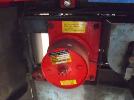
i upload my txr5 doc to AI this is what it cam up with
Good detail in your notes — I can piece this together from the TXR5 docs you uploaded.
On a Schindler Miconic TXR5, the red 12V wire at ACUMNA X3-1-1-8 is the supply line for the governor-mounted tach/encoder. That board needs a regulated 12 VDC feed to power its internal electronics so it can send quadrature signals (A/B channels) back to the ACUMNA/ASILOG for motion and speed reference.
Why the car faults with it connected:
If the tach has contamination (as you found with filings) or an internal failure, it can put noise or a short on the 12 V line.
When powered, the encoder outputs bad or inconsistent pulses. The CPU then thinks it lost encoder reference and throws System Encoder Fault (ACUMNA status “9”).
That’s why with the 12 V applied, it faults almost immediately.
Why the car runs with the 12 V disconnected:
With the supply removed, the tach is dead, so it produces no garbage signals.
The controller will then fall back to motor encoder feedback only. The system is redundant — the motor tach gives velocity and position, while the governor tach is used mainly for overspeed protection, rollback, and learn runs.
You can run like this temporarily, but you lose that redundancy. Certain features (learn trip, overspeed monitoring, accurate floor map integrity) won’t be valid without a functioning governor encoder.
What this means for you:
The red 12 V wire is not “just extra” — it’s the power source for the governor encoder.
The reason you can run without it is because the system still has the motor tach as primary reference. But long-term, you need both encoders healthy for full safety and proper hoistway synchronization.
If the tach is noisy even after cleaning, odds are the sensor board inside is damaged. Unfortunately, replacement is usually required.
👉 My recommendation:
Verify 12 V at X3-1-1-8 is clean and stable with no drop.
With the tach connected, scope the A/B channels at the ASILOG inputs — you should see clean quadrature square waves. If they’re irregular, the tach is bad.
If you can’t source the exact Schindler part, sometimes the encoder module itself (inside the governor tach housing) can be cross-referenced and replaced.
Would you like me to pull the pinout for X3-1-1 so you can see exactly which pins are supplying and receiving the encoder signals? That way you can check if just the power or if the signal channels themselves are dragging it down.